Instrument Overview
Design
The design of SolPol is quite robust and follows that of its astronomical counterpart and predecessor, PlanetPol (Bailey et al., 2008; Hough et al., 2006).
The entire assembly can be rotated about its optical axis by 45 degrees for the complete Stokes vector measurement and so that biases can be removed.
SolPol measures the polarization fractions of linear polarization - expressed by the Q and U Stokes parameters - and circular polarization - expressed by the V Stokes parameter - from the whole solar disk and the entirety of the atmospheric column, depending on its limiting field-of-view aperture and the choice of mounting telescope.
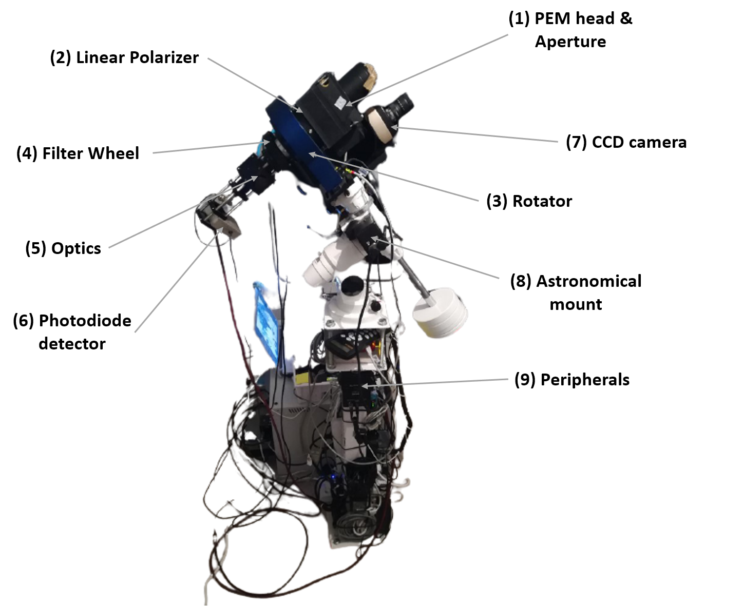
The polarimeter assembly includes:
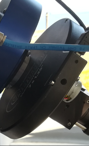
a Photo Elastic Modulator (PEM) head with a field of view limiting aperture,
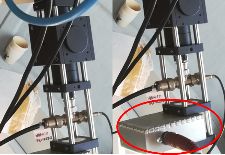
a Linear Polarizer (LP),
a field camera Rotator,
a filter wheel with several Neutral Density (ND) filters,
an imaging Galilean telescope,
a large area photodiode detector,
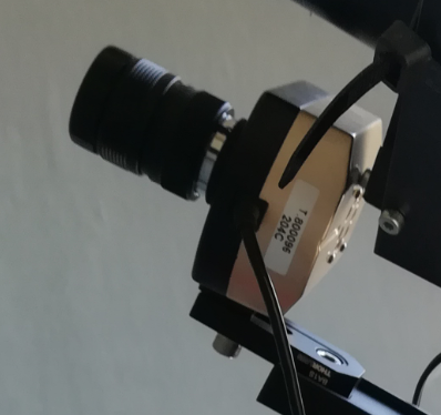
a CCD camera for effective Sun tracking,
an EQ3 equatorial astronomical mount with SynScan,
Peripherals for data acquisition →
a low-noise amplifier
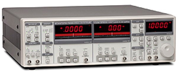
an oscilloscope
a servo stepper motor controller
an Analog-to-Digital Converter (ADC)
the PEM head controller, and
a PC-based control unit
Tip
Familiarize
SolPol is a complex instrument to the untrained eye. Take some time to visually recognize the instrument components !
There are no optical elements before the PEM, followed by the linear polarizer (see optical path pic). The ND filters establish the signal levels at the 1 cm silicon diode detector, which uses a transimpedance amplifier to generate the signal voltage.

Light beams meet from left to right: 5.5 mm aperture stop, PEM, linear polarizer, neutral density filters, Lens 1 & 2 Galilean telescope, 3.5mm field stop, photodiode detector.
The filter wheel contains six filters: 3 x RGB broad band filters with measured transmission curves - 3 x 40 nm narrow band filters at 400, 550, and 700 nm centre wavelengths.
Note
Spectral range
SolPol currently operates only at 550 nm.
Then, the 12-bit ADC records the diode signal and the lock-in amplifier records the first and second harmonic modulation signals, which are modulated by the PEM. Polarizer position and instrument rotation are controlled from a LabView virtual instrument program, which also controls data recording.
A video of SolPol slewing towards the Sun !
Measurements
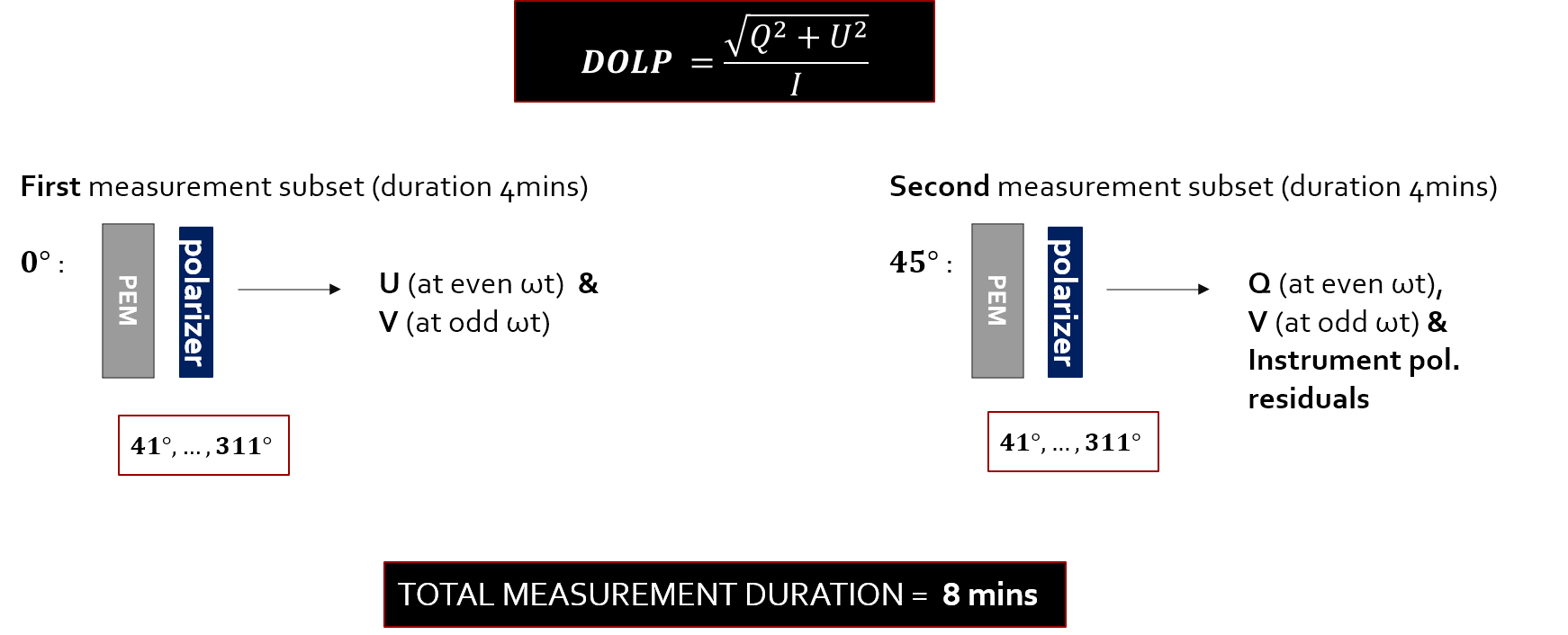
The first observing sequence is performed with the assembly at the rest position (0°) and the rotating of the linear polarizer in steps of 90° (see Instrument Rotation schematic). For a complete polarizer rotation of 360 degrees, the instrument acquires measurements for four minutes. The specific sequence provides measurements of three of the four Stokes parameters, I, Q and U.
This is followed by the second observing sequence, performed after the rotation of the entire assembly, about the PEM crystal optical axis, over 45°. This observing sequence provides measurements of the fourth Stokes parameter, V and measurements for the removal of the biases and residual polarizations due to high frequency strain of the PEM for another four minutes.
Tip
Each full measurement cycle has a duration of eight minutes.
Ultimately, in this duration we measure the voltage output (in Volts) from the DC and AC channels of the lock-in apmlifier. This translates to:
where Jn(A) are the n-order Bessel functions, specifically, J1(A) = 0.7342 and J2(A) = 0.6106 are the channel efficiencies.
Also:
since one must always subtract the mean DC signal of the Dark Measurements performed from the regular measurement.
If you are keen on learning the mathematical derivation of all measurement parameters, go to SolPol Principle of Operation.
Capabilities & Specifications
The capabilities of direct sun polarimetric measurements are discussed in Kemp et al. (1987) and Kemp and Barbour (1981), setting the detection threshold as low as sensitivities of the order of 10-7, for perturbations to the polarization of the forward scattered light.
SolPol measures the degree of linear and circular polarization, i.e., DOLP and DOCP, with an absolute accuracy of 1% and precision of 1 part per million (ppm) in polarization terms (see SolPol Principle of Operation).
It can be installed and operated 24/7 in diverse environments, according to installation requirements (see Installation & Setup).
System Components
For the individual instrument parts and their technical specifications see below:
Hinds Instruments Photoelastic Modulator - Series II FS47 (Optical head & Electronic head),
Material: Fused siclica resonant crystal with stress-induced birefringence
Operation Range: 400 nm -750 nm
Stress-type: Mechanical via standing acoustic waves by transducer at freq. of 47 kHz
Principle: Different polarization states are refracted on different directions due to birefringence
Light-path: Fundamental vibration along the crystal optical axis
Use: Can be used as any retardation plate between \(\lambda\)/4 to \(\lambda\)/2
Modulation efficiencies: 0.7342 (\(\omega\)) and 0.6106 (2\(\omega\)) - same for dark measurements
Cost: ~ 12 k£
Note
For a detailed description of the PEM operation go to PEM operation principle.
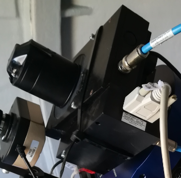
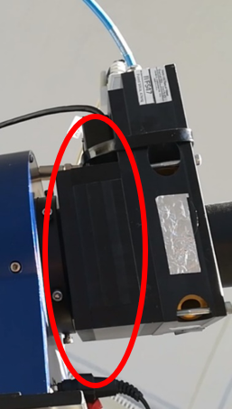
Rotatable Thorlabs Film Linear Polarizer,
optical axis initially aligned with PEM axis
attached to Thorlabs Heavy Duty rotation stage (see pics)
rotated through a Thorlabs K-cube stepper motor controller for 41° to 311°
rotation control by the APT Thorlabs software
Optec Inc. PYXIS 3-inch camera field rotator.

The Pyxis is a simple rotator used to attach CCD cameras on large telescopes for rotating the viewing field of the camera on long exposures. In SolPol, it is used to rotate the entire instrument assembly from 0° to 45°.
NAUTILUS Rotating Filter Wheel,
Available slots: 7
3 x RGB broad band filters
3 x 40 nm narrow band filters at 400, 550, and 700 nm
Current operation: at 550 nm
Galilean Telescope and 1-cm silicon Photodiode detector.
OpticStar CCD camera for Sun tracking, controlled by the OpticStar view software.
SR830 DSP Lock-In Amplifier, amplification through transimpedence.
Hinds Instruments PEM 100 head controller unit
Instrument Rotation
The measurement sequence of SolPol includes a rotation of the whole instrument assembly by 45° from the zero position (see XX). The relative position of the PEM and linear polarizer for each rotation state, is shown in the following figure.
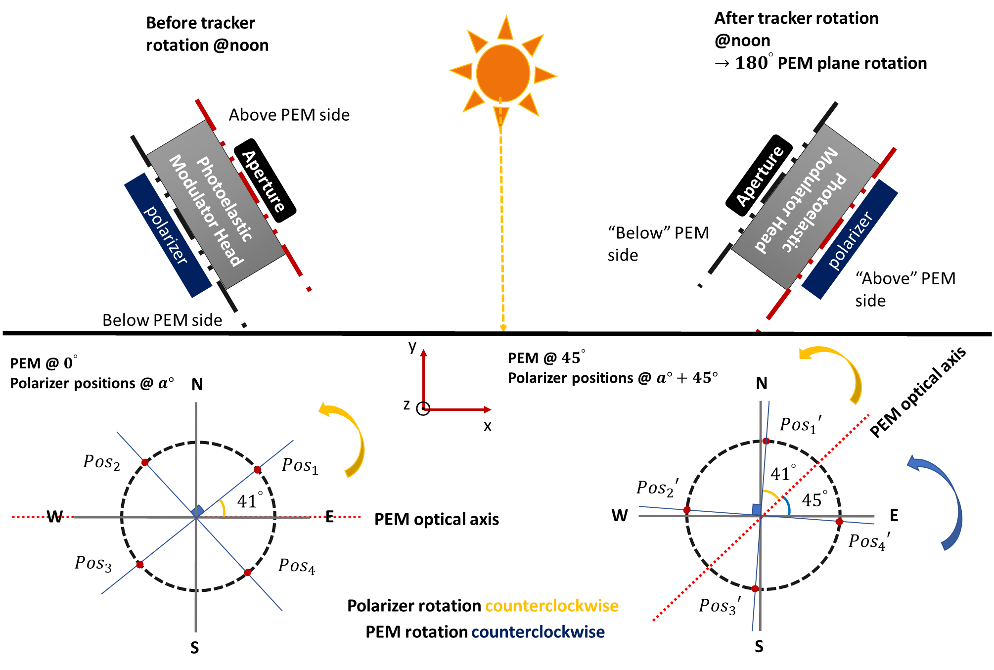
SolPol assembly positioning as seen from the incoming sunlight reference frame. Left arrangement: The initial sequence begins with the PEM and linear polarizer at the rest position of 0°, then the polarizer rotates by 90° starting from 41° (Pos1), to 131° (Pos2), 221° (Pos3) and 311° (Pos4) counter-clockwise. A complete polarizer rotation with the PEM at 0° provides measurements of the U Stokes parameter. Right arrangement: assembly rotation by 45° and subsequent similar rotation of the polarizer by 90° intervals from Pos1’ to Pos4’. This configuration provides measurements of the Q Stokes parameter.