Installation & Setup
SolPol has three installation modes:
Mode (1) at controlled laboratory conditions,
Mode (2) at observatories where it can be operated under diverse conditions, and
Mode (3) as a mobile instrument on experimental campaigns
All three modes share similar installation characteristics and can be adapted according to demand.
Below, you can find the complete installation guide of SolPol, either as a standalone instrument or as part of a general housing.
Instrument Needs
Power Needs
Power supply: Mains 220 V AC / 50 Hz
Default outlet: three-pin type G (UK optional, can be changed with multiple adapter options)
Power consumption: (?)
Mounting
Current: Skywatcher EQ3 SynScan GoTo equatorial mount.
Recommended upgrade: Skywacther HEQ5 Pro SynScan GoTo equatorial mount for better stability and tracking accuracy.
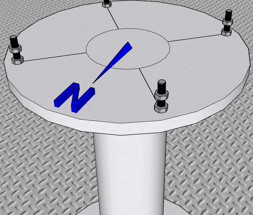
Permanent platform: a steel base that fits the EQ3 adapter should be built for the instrument beforehand with a clear positioning towards the true North.
See the following sketch of a custom base:
Tip
Consider Re-Designing
If you’re planning a mount upgrade, take this opportunity to consider a re-design.
Tripod: standard steel tripod for EQ3-2 mounts, mobile.
Data Transfer
Through PC control via Ethernet/ WiFi: approx. 10 Kb/s
Remote access capabilities via remote clients, e.g. Windows Remote Desktop, Anydesk etc.
Software
OS: Windows 10
Current state:
solpol.exewith Windows 10 drivers
Physical Installation Requirements
We will specify the basic physical requirements and space needs for SolPol.
Caution
Do not plug in any power or connection cables at this stage. Ensure all connections are made after following the proper setup procedures to avoid potential damage or hazards.
Mode (1)
When in Mode (1) a typical optical table will suffice for the instrument set-up. Custom solutions can be applied on spot.
Mode (2)
if SolPol operates as a standalone, then at least a 3-meter astronomical dome is advised for the instrument protection from extreme weather conditions.
(see
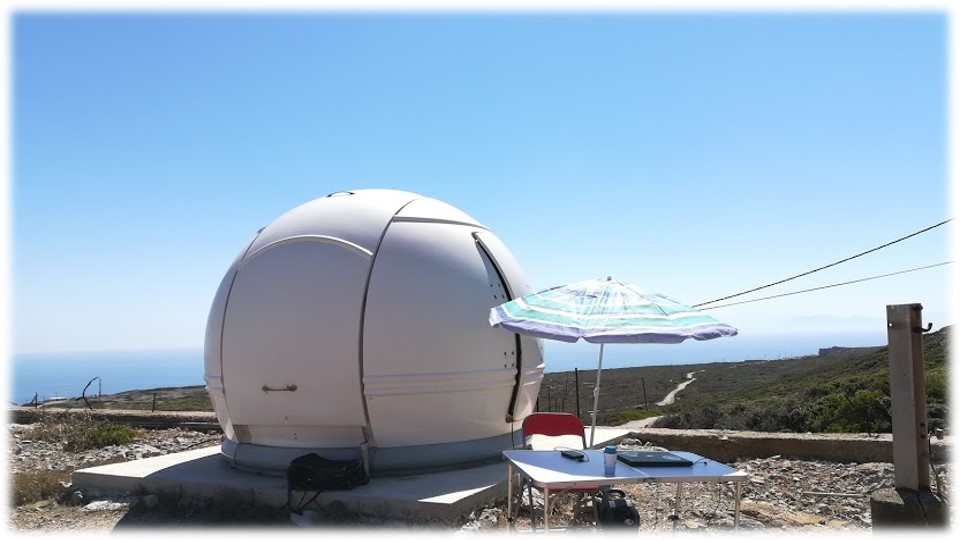 &
&  set-up at the PANGEA observatory, Antikythera)
! Proceed by initially configuring the astronomical mount on the designated base, followed by firmly securing the instrument.
Place mount on the base, adjust to base adapter until perfect fit.
Tighten base skrew and simultaneously adjust the EQ azimuth fine adjustments so that the mount points to marked true North.
Adjust mount latitude indication by the altitude adjustment bolts, wrt the installation location.
Tighten both mount brakes on “Home position”.
Handle SolPol carefully from the rails and place it on the top side of the mount.
Secure SolPol on the mount by completely tightening the base screw and then fine tune with the smaller side skrew until tight.
Re-check latitude indication and mount buble level.
Loosen azimuth brake by carefully holding the instrument and make sure it is completely balanced in the horizontal direction.
Retract to initial position and secure brake again.
Perform polar alignment.
Tip
For optimal results, it’s recommended to typically perform Polar alignment every night with clear skies, just before each scheduled measurement day.
if SolPol operates as part of an astronomical telescope, then it should be mounted after the telescope beam.
(see the
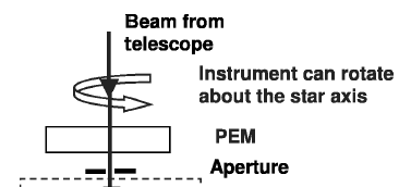 for telescope set-up of the SolPol predecessor, PlanetPol)
Mode (3)
When in Mode (3) and if there is no allocated housing with the above specifications for the instrument, use the tripod configuration as follows:
Secure a 3x3 m flat space, that will ensure Sun tracking with no obstacles in the instrument line-of-sight - preferably on a building rooftop.
Fully extend tripod legs and loosen the base skrew.
Fix astronomical mount to the tripod, by securing tightly the base skrew and adjusting the EQ azimuth fine adjustments.
! For EQ3: mount weights should be secured to the outmost far position of the bracket for SolPol balancing.
Mark the Magnetic North (N) with a compass and adjust the tripod so that the mount polarscope is roughly aligned with it.
Temporarily tighten both mount brakes on “Home position”.
Place the tripod firmly on the ground (looking to the North) and level according to tripod bubble indication.
Tip
Offset Acceptance and Compensation
A few degrees of offset are acceptable and will be compensated for through the Polar alignment process.
Secure tripod with master lock tie-downs at each side, as shown in the picture.

Attention
At this point, tripod leveling is likely compromised. Double-check the tripod bubble level, and consider re-adjusting it using an external level to ensure accurate alignment.
Secure SolPol on the mount rails by completely tightening the base screw and then fine tune with the smaller side skrew until tight.
Adjust mount latitude indication by the altitude adjustment bolts, wrt the installation location.
Loosen azimuth brake by carefully holding the instrument and make sure it is completely balanced in the horizontal direction. Retract to initial position and secure brake.
Recheck instrument alignment and leveling.
Perform polar alignment.
Electrical Setup & Connectivity Guidelines
SolPol, in its current version, is a bit complex in terms of connectivity and cable management as it relies on peripherals for the rotator control, filter usage and eventually the signal acquisition.
Cable Inventory
Tip
All USB cables and RS232 - RJ11 connectors are labelled in each end. Match cable codes with SolPol components.
2 x RS232-to-RS232 long cables (beige)
1 x BNC Male-to-Male cable short (blue)
1 x 4-pin S-Video Male-to-Female cable long (brown)
3 x BNC Male-to-Male long cables (black)
1 x Adapter BNC Male to 2 BNC Female
2 x IEC 60320 C13 & C14 power cords (black)
2 x Mini USB cables, short
2 x DC barrel jacks short (black)
3 x 12 VDC power supplies
2 x Type-B USB cables
(needs update…)
Attention
Cable color-coding may varry on latest instrument version !
Connect Instrumennt
The basic connection diagram of the instrument and its components is seen below:
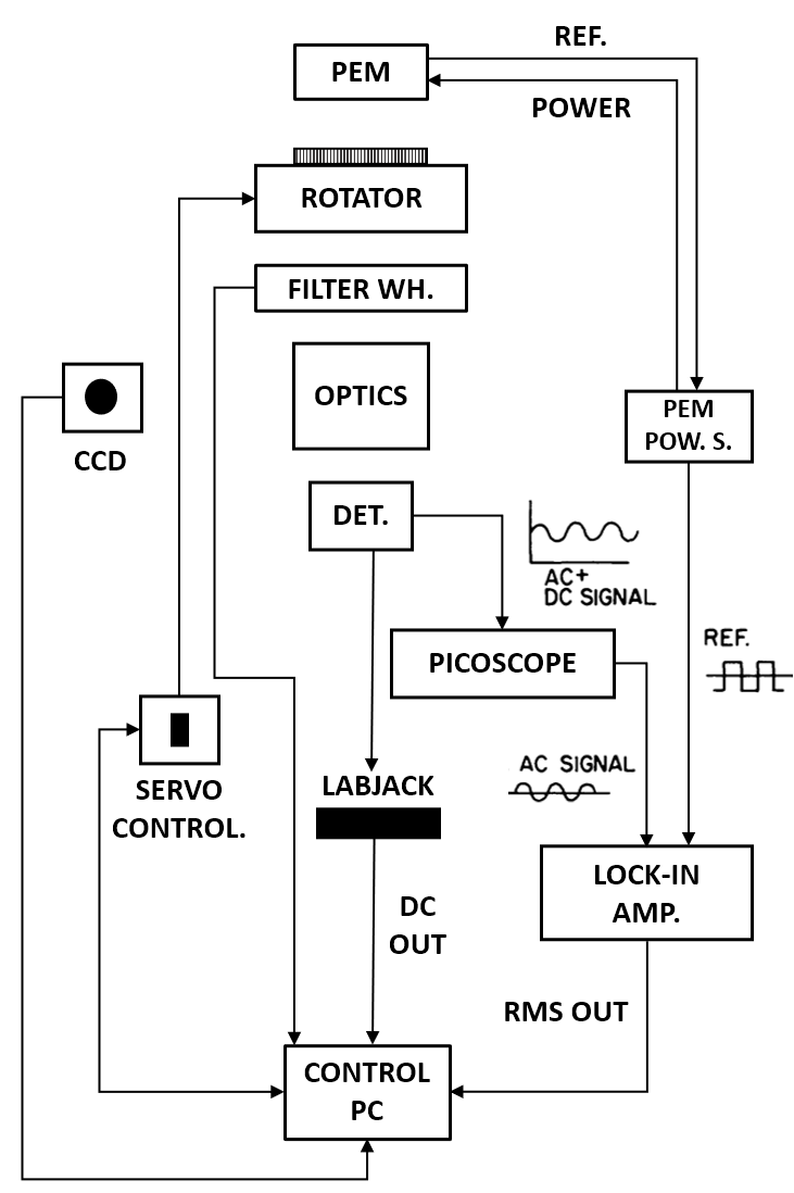
Let’s start top down !
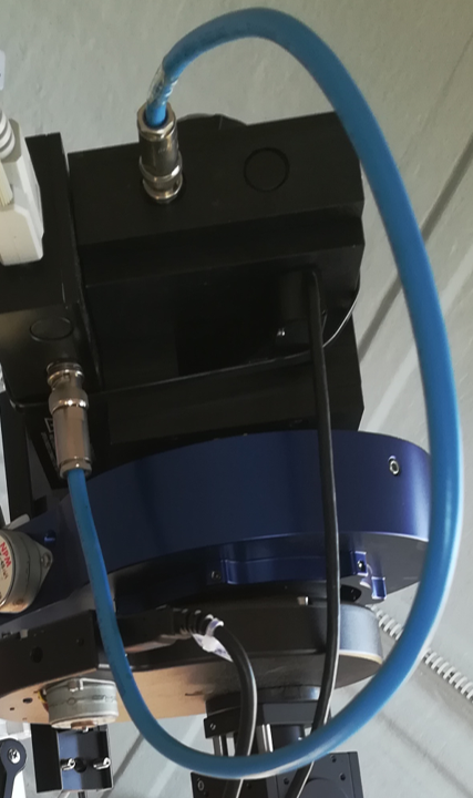
PEM Optical head connected to the Electrical head via a short BNC connector cable (light blue, usually on the PEM).
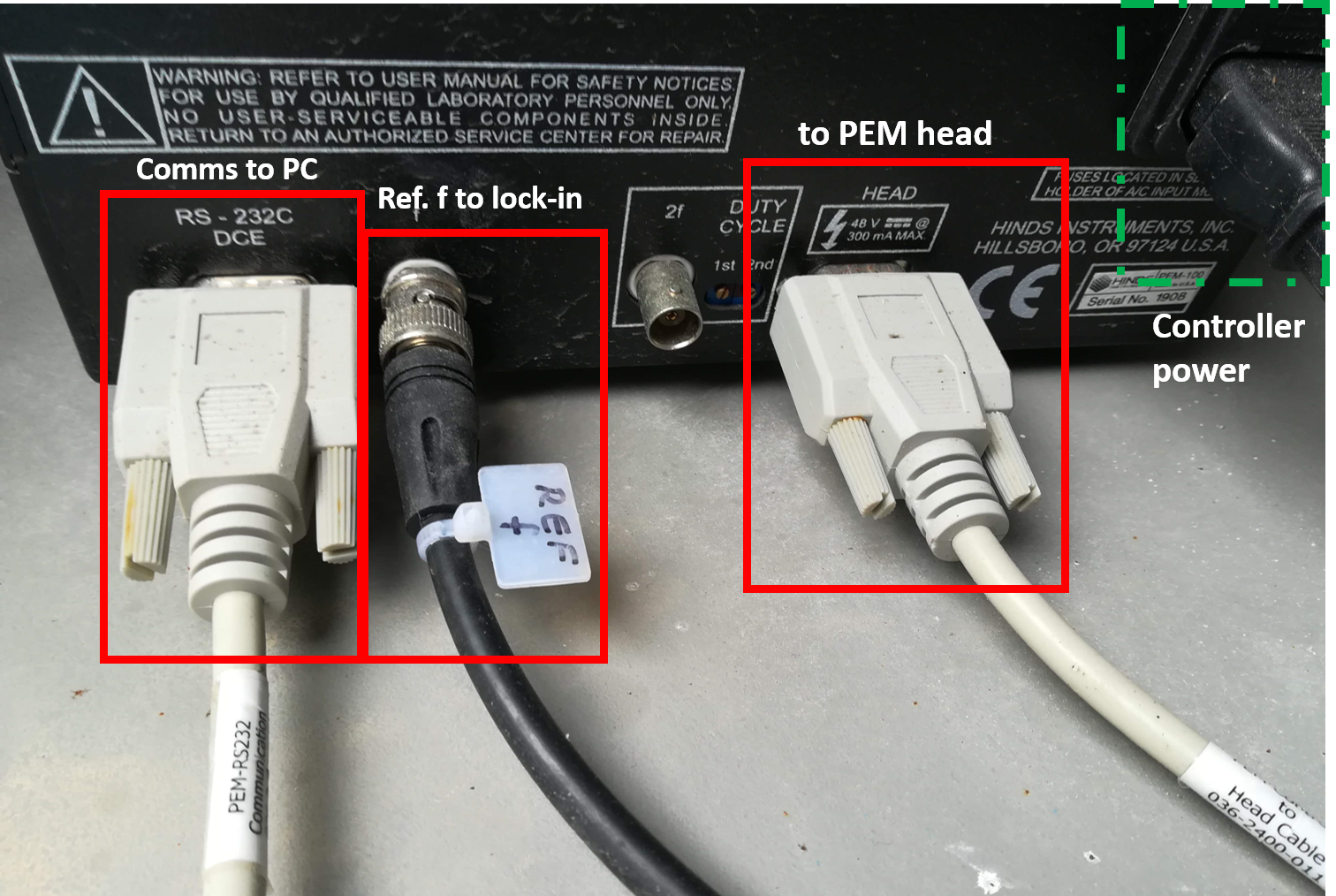
PEM Electrical head powered by the PEM controller via an RS232-to-RS232 connector cable
label: PEM HEAD, clr: beige
PEM Optical head communicates with the controller via an RS323C connector cable
DCE port, clr: beige
PEM controller gives reference frequency to the lock-in amplifier via a BNC cable
label: REF f, clr: black
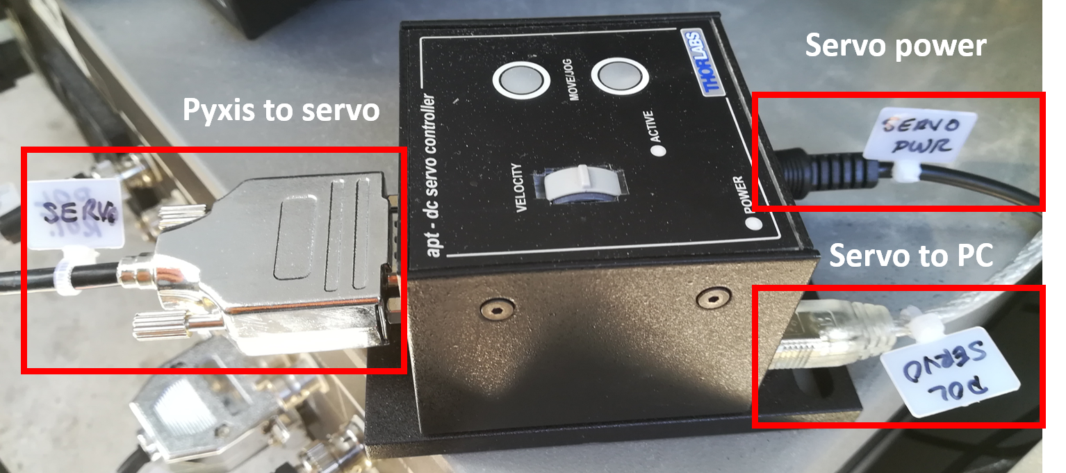
Rotator connected to Servo controller via an RJ11-to-RS232 cable for rotation control. Rotator powered via a 12 V DC power supply.
label: SERVO, clr: black
Servo powered via a 12 V DC power supply with barrel jack.
label: SERVO PWR, clr: black
Servo connected to PC control unit via a Mini USB cable.
label: POL SERVO, clr: black
Filter wheel connected to PC control for power & comms via Type-B USB cable.
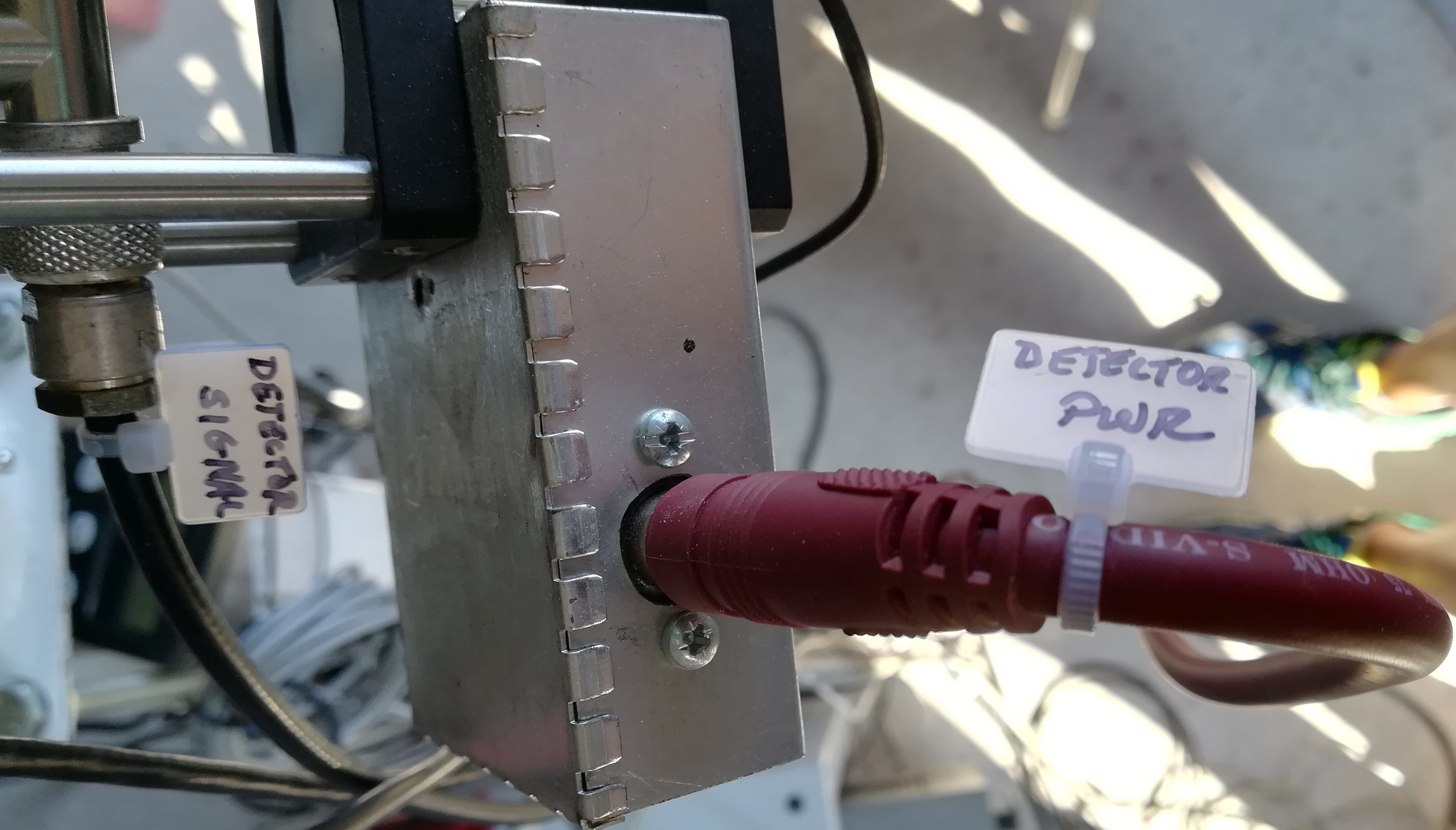
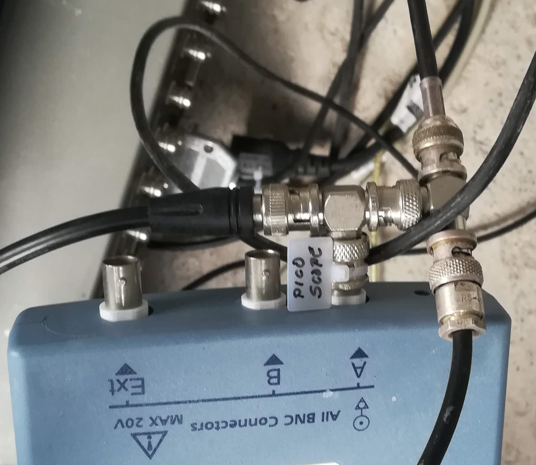
Detector power through S-Video cable, detector signal to picoscope and from there the DC part to labjack.
label: DETECTOR PWR, clr: brown, label: DETECTOR SIGNAL clr: black
Picoscope powered via a Type-B USB cable and BNC adapter Male to 2 Female connected to channel A for signal branching.
label: PICOSCOPE, clr: black
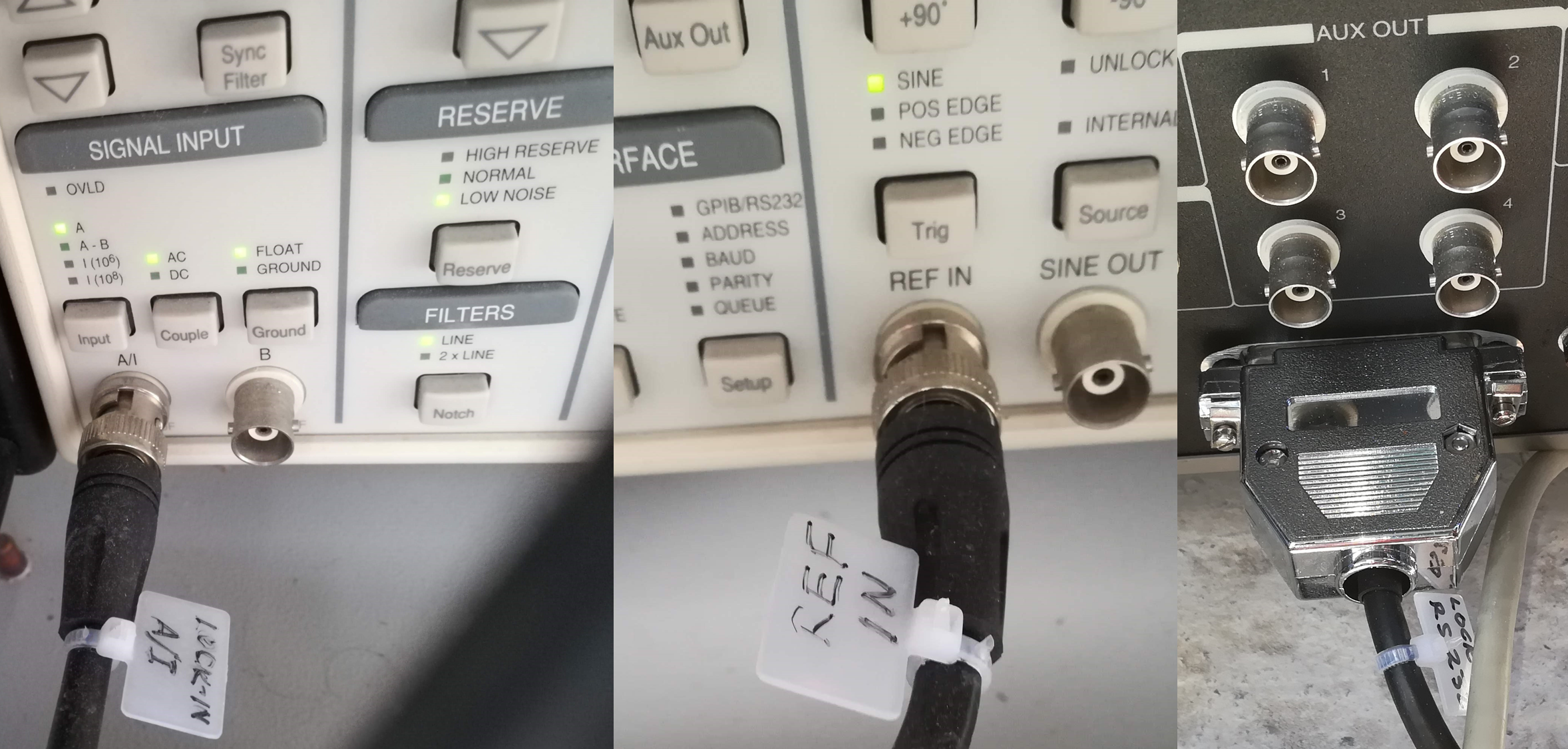
Lock-in powered by mains, reference frequency in from PEM and A/I in front lock-in side. Lock-in comms to PC control via an RS232 connector cable.
label: LOCK-IN A/I, clr: black, label: REF IN, clr: black, label: LOCK-IN RS232, clr: black
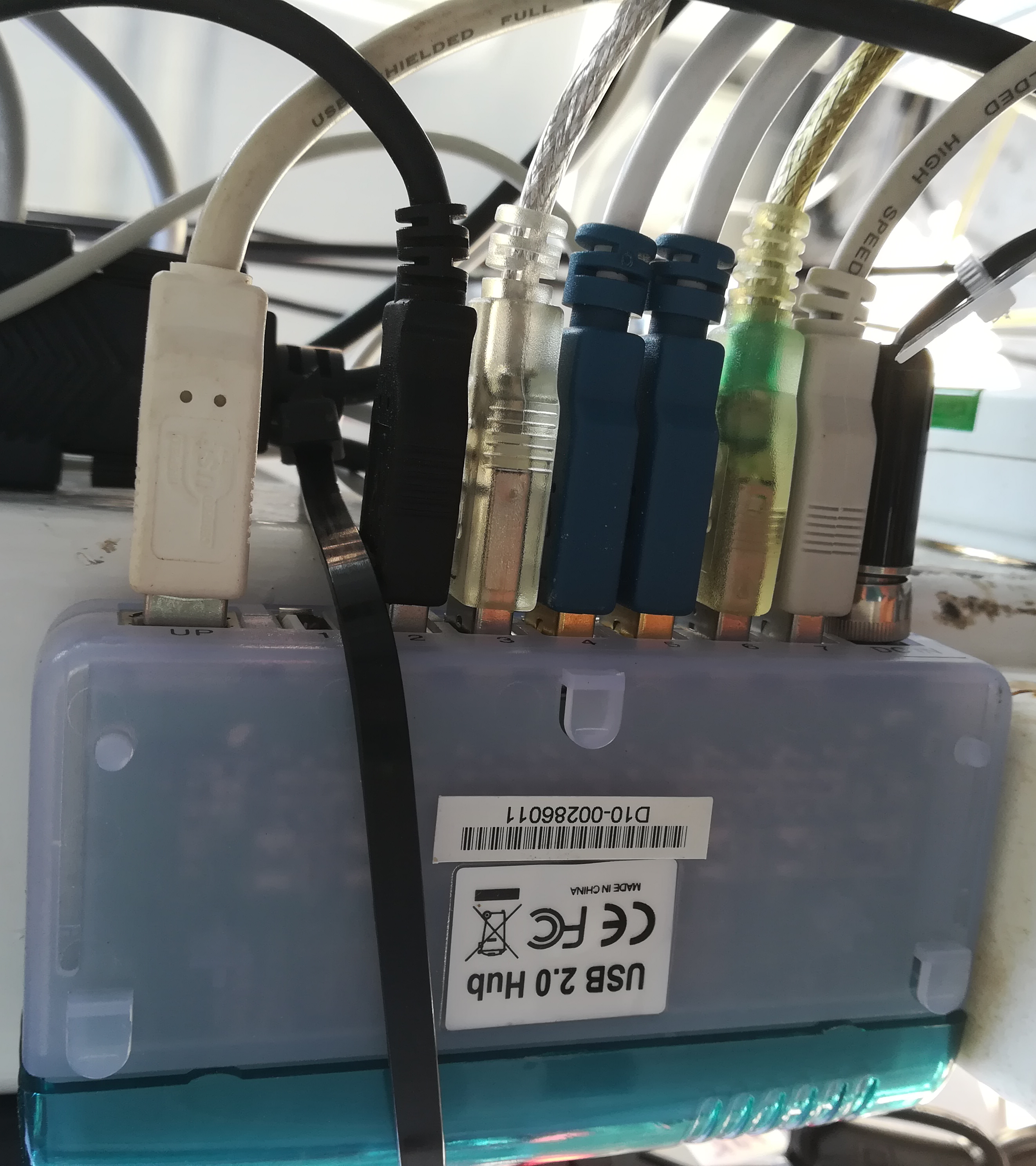
Labjack connection to detector on AIN1 and GND. Labjack powered by a Type-B USB cable.
label: LABJACK, clr: white

Eventually, after all USB cables are connected to the respective USB hubs or available PC ports, you will end up with something like this:
Connect Mount
Note
Remote connection
Tracker at its current state is controlled only via the PC by bypassing the hand-controller.
Connect mount motor cables, one way.
Connect the other motor cable to tracker controller.
Connect RJ45 port to EQdir adapter device for EQmod to bypass the hand-controller.
Power on EQdir via the mini USB cable to the PC control (red light on).
Connect tracker power supply.
Initialization sound on.
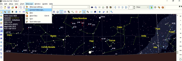
On PC control unit, open
CartesduCeil.exefree and open source planetarium program.If in Antikythera: Make sure on the top left corner of panel interface, it writes “PANGEA-Antikythera”.
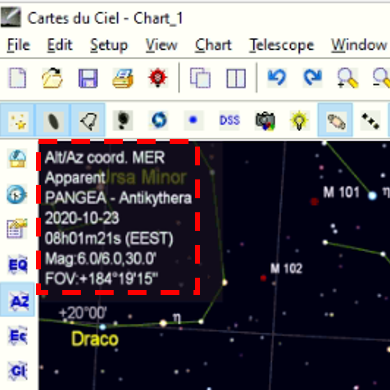
If in another observatory: Adjust accordingly from Cartes settings.
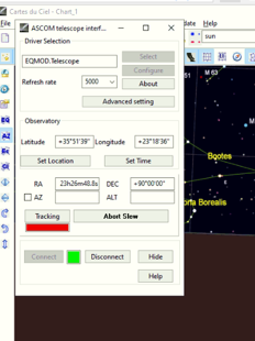
Grey ribbon tab press Telescope from dropdown → Connect Telescope → pops up ASCOM tab, press Connect → connection sound on.
How that looks:
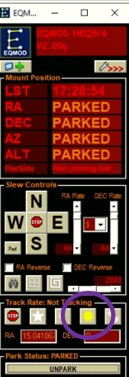
EQmod telescope tab pops → Parked sign on.
Tip
Home / Park position
Should be always the one from Mode (2)- Step 4.
! Tracking test sequence - duplicated in Track Object
Press ‘Unpark’ in Eqmod to unlock mount positioning.
Slew to object (Sun or for Any object process is the same):
In CartesduCeil search tab insert Sun and find in planetarium → right click in Sun’s position → select Telescope → Slew: Sun

Caution
Tracker Slewing
Tracker starts moving towards Sun, beware of jammed cables !
Enable solar tracking → press track rate Solar.
Calibration Procedures
There are a few calibration procedures for SolPol that can be performed under ambient measurement conditions and are imperative for the instrument smooth operation.
The absolute calibration procedures for the PEM crystal’s peformance or the broader optical parameters of SolPol (e.g. radiometric or temperature calibration) are not covered within this manual’s scope. These processes necessitate dedicated infrastructure and in-lab preparations.
Polar alignment
This procedure is a standard process for most astronomical instruments and ensures consistent object tracking, especially for the case of SolPol that is designated to track the solar disk for extended periods of time. It is performed under clear night skies by recognizing the position of Polaris (\(\alpha\) Ursae Minoris) and fine tuning the astronomical mount.
It should be performed typically after each measurement day, if applicable !
For a comprehensive tutorial follow the link !
Sun Centering
In order to track the Sun with a stable rate through the day, we need to center it on SolPol’s FOV. This is an instrument specific sequence and we are aided by the CCD camera, which is aligned with the instrument in the mount rails.
For the Sun centering process follow the steps:
Power-on tracker and initialize track Sun sequence → see details in Connect Mount .
Power-on the CCD camera by connecting the USB on PC operation.
Remove the lens protective cover.
Place Sun filter in front of the camera lens (if not already installed).
Double-click on
Opticstar Viewinterface icon.This should open the following window:
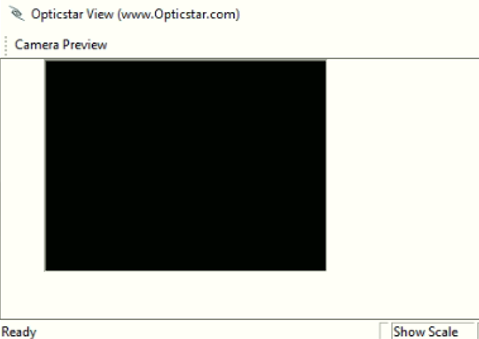
Sun might not appear immediately on screen
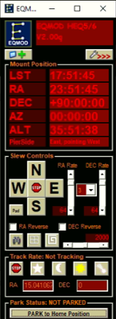
At EQmod tab press N-S & W-E buttons for tracker to move (see pic).
Slowly bring Sun to the CCD’s panel.
Note
Depending on the Sun’s position it will appear in a different place on the camera panel.
Open the oscilloscope from
picoscope.exe, which should show a voltage range like in the picture if the Sun is not centered: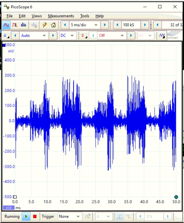
Adjust Sun’s position to the point where the signal in Picoscope is maximized and leave CCD panel open to Desktop.
max. at mean 12 V (without an ND filter)
optimal position at camera panel center
Laslty, visually check if the instrument is pointing towards the Sun’s center.
Tip
Good Practice
Make sure on large tracking durations that the Sun remains on the same spot in the screen. This means that an optimal polar alignment was performed.
If Sun diverges significantly during or after each measurement, repeat steps !
Dark Measurements
Dark measurements involve taking readings or images when no light or signal is present, essentially capturing the instrument’s inherent noise or baseline signal. These measurements help account for any sensor noise, electronic noise, or other background signals that might affect the accuracy of subsequent measurements.
By subtracting the dark measurement data from the actual measurements, the instrument’s true signal can be more accurately determined.
As in any other polarimeter, SolPol dark measurements should be performed before AND after each measurement sequence to ensure a dense dataset for comparison. These measurements are best performed with:
Prerequisites
A closed dome shutter.
The mount is properly powered and tracking.
Installation of a darkening shutter that completely covers the SolPol aperture.
Note
To better comprehend the Dark Measurements sequence, one must proceed to the Operation section and fully understand how to acquire a proper measurement with the instrument.
Therefore, for a detailed description go to → Prepare Measurement and repeat steps by simultaneously satisfying prerequisites (1) to (3).